|
|
| |
You are here: Home〉Products 〉Distribution Agent |
|
|
|
|
| Model: |
|
|
| 1 |
Models |
Flow Sensor |
| 2 |
Dental mouth diameter (both ends same) |
1:Rc1/8 2:Rc1/4 3:Rc3/8 6:Rc3/4 8:Rc1 |
| 3 |
For fluid |
O:Oil * W: water, water-soluble coolant |
| *FS-1 were used to prepare O- |
|
|
|
| Special length: |
| · |
In input power for the DC12 ~ 24V (allowable voltage change ± 10%) used within the scope of。 |
| · |
Amplifier protection structure IP67。 |
| · |
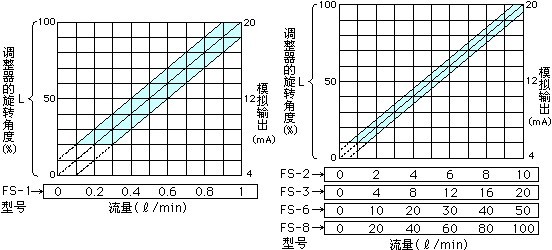
Lower limit can be set to flow。
Flow below the lower limit set, the red LED light (NG) display and a warning signal output contacts。 |
| · |
Output and analog output proportional to flow(4~20mA)。 |
| · |
Low standard rotation of the rotor can observe the situation confirmed that the flow of fluid status。 |
| · |
Specifications can be 25MPa high-pressure flow measurement. (Not including the FS-1) FS-2, 3,6,8 sure to install the cover B (High Pressure) used state. Factory installed cover B (high-voltage use)。 |
| · |
Can be installed in any state (horizontal, vertical, inclined) direction and free flow of use。 |
| · |
Remove the lid body can be clean in front of the rotor。 |
| Specification: |
| Model |
FS-1 |
FS-2 |
FS-3 |
FS-6 |
FS-8 |
| Connection diameter |
Rc1/8 |
Rc1/4 |
Rc3/8 |
Rc3/4 |
Rc1 |
| Flow Range |
0.2~1∮/min |
1~10∮/min |
2~20∮/min |
5~50∮/min |
10~100∮/min |
| Maximum pressure |
3MPa |
3MPa |
25MPa |
3MPa |
25MPa |
3MPa |
25MPa |
3MPa |
25MPa |
| Install cover* |
Cover A
PC/C3604 |
Cover A
PC/C3604 |
Cover B
C3604 |
Cover A
PC/C3604 |
Cover B
C3604 |
Cover A
PC/C3604 |
Cover B
C3604 |
Cover A
PC/C3604 |
Cover B
C3604 |
| Observation window function |
Have |
Have |
No |
Have |
No |
Have |
No |
Have |
No |
| Accuracy (full flow range) |
±0.1∮
/min |
±0.5∮
/min |
±1∮
/min |
±2.5∮
/min |
±5∮
/min |
| For fluid |
Lubricating oil |
Oil, water, cooling liquid |
| Operating temperature range |
0~80℃(Surrounding temperature 0~50℃) |
| Pressure Loss |
0.03MPa the following(at 32cst) |
0.025MPa the following(at 32cst) |
| Body Material |
C3604(NiNickel) |
| *:With cover A, B each one. Factory installed cover B. Under the pressure of following in 3MPa used to observe the fluid functions, please modify cover A. (Cover A, B of the proposed tightening torque 10N.m. Piping installed in the body of the state, remove the lid can not be removed even if the rotor。) |
|
| Using the flow sensor with amplifier (common) |
| Power |
DC12~24V(Allow voltage changes±10%) |
| Maximum current consumption |
max 100mA |
| Analog Output |
DC4~20mA(Maximum load resistance of 300 ohms) |
| Contact Output Capacity |
DC24V/0.2A(No-voltage contacts B) |
| Limit setting range |
Can set the lower limit within the entire flow range ※1
Set minimum flows in the above case, the green LED light lit (OK), contact output (closed)ON
Set minimum flows in the following words, the red LED light lit (NG), contact output (open)OFF |
| Sensor line |
5, with 1 meter core protection cord ※2
①Input Power +DC12~24V
②DC0V
③Analog Output(+4~20mA)
④⑤Lower limit contact output
<Wiring diagram> |
| |
.jpg) |
| Amplifier protection structure |
IP67 (Protection class) |
| Amplifier Material |
ABS |
※1:Please disconnect the plug, use a screwdriver in the lower limit alarm set on flow regulator. (Please use the flat screwdriver.)
Scale and range of values that flow。
※2:Wire length 1 m or more, please ask。 |
|
| Action principle |
.jpg) |
| The detection part of the flow sensor is used to set the fluid pathway“Rotor (turbine wing) and fluid flow in proportion to the rotation this. Measurement by setting the external part of the magnetic sensors detect the rotor installed in the periphery of the "permanent magnet" of the rotation. The output part of the standard equipment, with the rotation (flow) proportional to the analog output and contact output. |
|
| Caution |
| ● |
Please observe the maximum use of flow。 |
.jpg) |
| ● |
Avoid setting the formation of magnetic fields in the motors near the machine. Sometimes malfunction。 |
| ● |
Tube diameter at the upper reach of more than 10 times the straight pipe section, set four times higher than in the downstream straight pipe section. Please do not set near the entrance, "bends, T-tube, the throttle" and "bending, merging, some differences”。 |
| ● |
| Flow Sensor |
Upstream straight pipe section |
Downstream straight pipe section |
| FS-1 |
100 |
40 |
| FS-2 |
140 |
60 |
| FS-3 |
170 |
70 |
| FS-6 |
270 |
110 |
| FS-8 |
340 |
140 |
|
| ● |
Rotor containing a magnet. Please use the oil, then set about 5 to 20 micron filter, using coolant, then, set about 20 to 50 micron filter。 |
| |
※Purports to contain a large number Fenxie coolant such as General NC lathes, grinders, etc., please ask to our sales department。
※Fen Xie and in case of attachment of the rotor is not rotating, please remove the lid in front of the body, attached to the rotor blast cleared the Fen Xie。 |
|
| Use Cases |
| ● |
Management of a variety of machine tools, printing machines, stamping machines, gear shaft, etc., all bearing the oil flow to prevent burning。 |
| ● |
Management of a variety of machine tool coolant flow in order to prevent damage, fire。 |
| ● |
Used to detect filter clogging。 |
| ● |
Cooling water flow management。 |
|
| Concerning the accuracy |
General for moving oil 32cst/0 Specification
Clear water at room temperature /W Specification |
| ●The factory in order to detect these conditions. Please refer to the flow sensor accuracy specifications。 |
|
|
|
|
|
|
|
|